Sensor Porting Guide
1. Overview
This document describes how to porting SigmaStar sensor driver including basic hardware knowledge, software control sensor API(sensor handle), sensor interface API(Sensor-IF) of SigmaStar and software porting flow. In this document, we take the sensor driver of imx415/imx307/os550xs as examples. You can follow the instructions in this document to complete the sensor porting step by step.
First we introduce the relevant knowledge of hardware and corresponding source code to make it easier to understand for you.
2. Sensor Hardware (Take imx415 sensor as an example)
2.1. Power On Sequence in Datasheet
-
Turn On the power supplies so that the power supplies rise in order of 1.1V power supply (DVdd) → 1.8V Power supply(OVdd) → 2.9V power supply(AVdd). In addition, all power supplies should finish within 200ms.
-
The register values undefined immediately after power-on, so the system must be cleared. Hold XCLR at low level for 500ns or more after all the power supplies have finished rising. (The register values after a system clear are the default values.)
-
The sys clear is applied by setting XCLR to High level. The maser clock input after setting the XCLR pin to High level
-
Make the sensor setting by register communication after the system clear

2.2. Schematic of Power Circuit
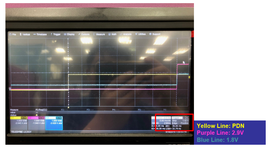
Below is SigmaStar Sensor board schematic of power circuit. 1.1V, 1.8V, 2.9V power will pull high after power-on enable. First 1.1V, then 1.8V and 2.9V, you can use an oscilloscope to measure it on your sensor board.

2.2.1. IMX415 Power ON Measurement(1)

2.2.2. IMX415 Power ON Measurement(1)
3. Sensor Code Setting
3.1. pCus_poweron API
You can control sensor power-on and reset pins through "handle->pCus_sensor_poweron" in the sensor driver handle initial function. If you need to modify sensor power sequence timing, please check the characteristics of sensor and hardware design.
static int pCus_poweron(ms_cus_sensor *handle, u32 idx)
{
    ISensorIfAPI *sensor_if = &handle->sensor_if_api;
    //SENSOR_DMSG("[%s] ", __FUNCTION__);
    printk("[%s] ", __FUNCTION__);
    //Sensor power on sequence
    sensor_if->PowerOff(idx, handle->pwdn_POLARITY);   // Powerdn Pull Low
    sensor_if->Reset(idx, handle->reset_POLARITY);     // Rst Pull Low
    sensor_if->SetIOPad(idx, handle->sif_bus, handle->interface_attr.attr_mipi.mipi_lane_num);
    sensor_if->SetCSI_Clk(idx, CUS_CSI_CLK_216M);
    sensor_if->SetCSI_Lane(idx, handle->interface_attr.attr_mipi.mipi_lane_num, ENABLE);
    sensor_if->SetCSI_LongPacketType(idx, 0, 0x1C00, 0);

    if (handle->interface_attr.attr_mipi.mipi_hdr_mode == CUS_HDR_MODE_SONY_DOL) {
        sensor_if->SetCSI_hdr_mode(idx, handle->interface_attr.attr_mipi.mipi_hdr_mode, 1);
    }

    sensor_if->PowerOff(idx, !handle->pwdn_POLARITY);
    //Sensor board PWDN Enable, 1.8V & 2.9V need 30ms then Pull High
    SENSOR_MSLEEP(31);
    sensor_if->Reset(idx, !handle->reset_POLARITY);
    SENSOR_UDELAY(1);
    sensor_if->MCLK(idx, 1, handle->mclk);
    printk("Sensor Power On finished\n");
    return SUCCESS;
}
3.1.1. Handle of signal polarity API
Set Soc hardware signal polarity
| Parameter | Description | Note |
|---|---|---|
| handle->pwdn_POLARITY | Register set output sensor power-down pin (GPIO) polarity | SENSOR_PWDN_POLCUS_CLK_POL_POS = 0,/** High active */CUS_CLK_POL_NEG/** Low active */ |
| handle->reset_POLARITY | Register set output sensor reset pin (GPIO) polarity | SENSOR_RST_POLCUS_CLK_POL_POS = 0,/** active */CUS_CLK_POL_NEG /**Low active */ |
For parallel Interface
| Parameter | Description | Note |
|---|---|---|
| handle->VSYNC_POLARITY | Register set receive sensor Vsync pin signal polarity | SENSOR_VSYNC_POL CUS_CLK_POL_POS = 0, /** High active */ CUS_CLK_POL_NEG /** Low active */ |
| handle->HSYNC_POLARITY | Register set receive sensor Hsync pin signal polarity | SENSOR_HSYNC_POL CUS_CLK_POL_POS = 0, /** High active */ CUS_CLK_POL_NEG /** Low active */ |
| handle->PCLK_POLARITY | Register set receive sensor pixel clk pin signal polarity | SENSOR_PCLK_POL CUS_CLK_POL_POS = 0,/** High active */CUS_CLK_POL_NEG /** Low active */ |
3.2. I2C Info and Setting
SigmaStar SoC needs to communicate with a sensor through I2C, please check the sensor I2C slave address first.

3.2.1. Corresponding source code
The sensor driver I2C Setting in Marco define
////////////////////////////////////
// I2C Info                       //
////////////////////////////////////
#define SENSOR_I2C_ADDR              0x34               //I2C slave address
#define SENSOR_I2C_SPEED             300000             //I2C speed, 60000~320000
//#define SENSOR_I2C_CHANNEL         1                  //I2C Channel
//#define SENSOR_I2C_PAD_MODE        2                  //Pad/Mode Number

//usally set CUS_I2C_NORMAL_MODE,  if use old OVT I2C protocol=> set CUS_I2C_LEGACY_MODE
#define SENSOR_I2C_LEGACY            I2C_NORMAL_MODE
//CUS_I2C_FMT_A8D8, CUS_I2C_FMT_A8D16, CUS_I2C_FMT_A16D8, CUS_I2C_FMT_A16D16
#define SENSOR_I2C_FMT               I2C_FMT_A16D8

int cus_camsensor_init_handle_linear(ms_cus_sensor* drv_handle)

/////////////////////////////////////////////////////
// i2c config
/////////////////////////////////////////////////////
handle->i2c_cfg.mode          = SENSOR_I2C_LEGACY;    //(CUS_ISP_I2C_MODE) FALSE;
handle->i2c_cfg.fmt           = SENSOR_I2C_FMT;       //CUS_I2C_FMT_A16D8;
handle->i2c_cfg.address       = SENSOR_I2C_ADDR;      //0x5a;
handle->i2c_cfg.speed         = SENSOR_I2C_SPEED;     //320000;
NOTE: Check the sensor board schematic of I2C slave mode Option
3.2.2. Sensor MCLK suppot
Each sensor can support in different MCLK. The MCLK list table that we can provide is as follows. You can find the MCLK corresponding to the sensor from the initialization settings provided by the sensor vendor. The sensor MCLK Setting in Marco define
////////////////////////////////////
// MCLK Info //
////////////////////////////////////
/*******I5/I6 Support MCLK List*******
* CUS_CMU_CLK_27MHZ / CUS_CMU_CLK_21P6MHZ / CUS_CMU_CLK_12MHZ,
* CUS_CMU_CLK_5P4MHZ / CUS_CMU_CLK_36MHZ / CUS_CMU_CLK_54MHZ,
* CUS_CMU_CLK_43P2MHZ / CUS_CMU_CLK_61P7MHZ / CUS_CMU_CLK_72MHZ,
* CUS_CMU_CLK_48MHZ / CUS_CMU_CLK_24MHZ / CUS_CMU_CLK_37P125MHZ,
******End of Support MCLK List*******/
#define Preview_MCLK_SPEED CUS_CMU_CLK_27MHZ
#define Preview_MCLK_SPEED_HDR_DOL CUS_CMU_CLK_37P125MHZ
The sensor MCLK control Interface in handle initial function
////////////////////////////////////
// mclk //
////////////////////////////////////
handle->mclk = UseParaMclk(SENSOR_DRV_PARAM_MCLK());
3.3. Fill Up Initial Setting Flow
As follow, the init exel supplyed by sony vendors; and we need fill the init setting to Sensor driver's init table.

const static I2C_ARRAY Sensor_init_table_4lane_linear[] =
{
    {0x3000, 0x01},    //Standby
    //{0xffff, 0x24},    //delay (ms)
    {0x3002, 0x01},    //Master mode stop
    //{0xffff, 0x10},    //delay (ms)
    {0x3008, 0x7F},    //BCwait time
    {0x3009, 0x00},
    {0x300A, 0x5B},
    {0x300B, 0xA0},
…
…
…
    {0x4074, 0x01},
    {0xffff, 0x24},
    {0x3002, 0x00},    //Master mode start
    {0xffff, 0x10},
    {0x3000, 0x00},    //Operating
};
3.4. Sensor Register Initial Setting Flow

4. Software Sensor Driver
This chapter introduces the process of software porting sensor driver. First, it will explain how to initialize the sensor. Then describe the information required by the sensor driver 3A and control the functions that 3A will call.
4.1. Sensor Driver Entry and support mode
Register the sensor support behavior mode. For example, the IMX415 sensor supports linear and HDR mode, you can refer to the IMX415 sensor driver and fill it in define of “SENSOR_DRV_ENTRY_IMPL_END_EX”.

| Parameter | Description |
|---|---|
| Name | Sensor Name and support mode |
| LinearEntry | Sensor Linear mode handle initial function |
| HdrSefEntry | Sensor HDR Short Exposure handle initial function |
| HdrLefEntry | Sensor HDR Long Exposure handle initial function |
| PrivateDataType | Sensor Private Data Type |
4.2. Sensor-IF Information
These settings are the hardware infomation of the sensor, we have listed the necessary hardware information, you can refer to the IMX415/IMX307 sensor driver
////////////////////////////////////
// Sensor-If Info                 //
////////////////////////////////////
//MIPI config begin.
#define SENSOR_MIPI_LANE_NUM        (4)
#define SENSOR_MIPI_LANE_NUM_DOL    (4)
//#define SENSOR_MIPI_HDR_MODE        (0) //0: Non-HDR mode. 1:Sony DOL mode
#define SENSOR_ISP_TYPE             ISP_EXT             //ISP_EXT, ISP_SOC (Non-used)
//#define SENSOR_DATAFMT             CUS_DATAFMT_BAYER    //CUS_DATAFMT_YUV, CUS_DATAFMT_BAYER
#define SENSOR_IFBUS_TYPE           CUS_SENIF_BUS_MIPI  //CFG //CUS_SENIF_BUS_PARL, CUS_SENIF_BUS_MIPI
#define SENSOR_MIPI_HSYNC_MODE      PACKET_HEADER_EDGE
#define SENSOR_MIPI_HSYNC_MODE_HDR_DOL PACKET_FOOTER_EDGE
#define SENSOR_DATAPREC             CUS_DATAPRECISION_10
#define SENSOR_DATAPREC_DOL         CUS_DATAPRECISION_12
#define SENSOR_DATAMODE             CUS_SEN_10TO12_9098  //CFG
#define SENSOR_BAYERID              CUS_BAYER_GB         //0h: CUS_BAYER_RG, 1h: CUS_BAYER_GR, 2h: CUS_BAYER_BG, 3h: CUS_BAYER_GB
#define SENSOR_BAYERID_HDR_DOL      CUS_BAYER_RG
#define SENSOR_RGBIRID              CUS_RGBIR_NONE
#define SENSOR_ORIT                 CUS_ORIT_M0F0        //CUS_ORIT_M0F0, CUS_ORIT_M1F0, CUS_ORIT_M0F1, CUS_ORIT_M1F1,
//#define SENSOR_YCORDER              CUS_SEN_YCODR_YC     //CUS_SEN_YCODR_YC, CUS_SEN_YCODR_CY

////////////////////////////////////
// MCLK Info                      //
////////////////////////////////////
#define Preview_MCLK_SPEED          CUS_CMU_CLK_27MHZ    //CUS_CMU_CLK_24MHZ //CUS_CMU_CLK_37P125MHZ
#define Preview_MCLK_SPEED_HDR_DOL  CUS_CMU_CLK_27MHZ
  int cus_camsensor_init_handle_linear(ms_cus_sensor* drv_handle)
4.3. Sensor-IF Information in handle
4.3.1. Macro Parameter
  int cus_camsensor_init_handle_linear(ms_cus_sensor* drv_handle)

 ////////////////////////////////////
 //    sensor interface info       //
 ////////////////////////////////////
 handle->isp_type    = SENSOR_ISP_TYPE;
 //handle->data_fmt    = SENSOR_DATAFMT;
 handle->sif_bus     = SENSOR_IFBUS_TYPE;
 handle->data_prec   = SENSOR_DATAPREC;
 handle->data_mode   = SENSOR_DATAMODE;
 handle->bayer_id    = SENSOR_BAYERID;
 handle->RGBIR_id    = SENSOR_RGBIRID;
 handle->orient      = SENSOR_ORIT;
 //handle->YC_ODER     = SENSOR_YCORDER;   //CUS_SEN_YCODR_CY;
 handle->interface_attr.attr_mipi.mipi_lane_num    = SENSOR_MIPI_LANE_NUM;
 handle->interface_attr.attr_mipi.mipi_data_format = CUS_SEN_INPUT_FORMAT_RGB; // RGB pattern.
 handle->interface_attr.attr_mipi.mipi_yuv_order   = 0; //don't care in RGB pattern.
 handle->interface_attr.attr_mipi.mipi_hsync_mode  = SENSOR_MIPI_HSYNC_MODE;
 handle->interface_attr.attr_mipi.mipi_hdr_mode    = CUS_HDR_MODE_NONE;
 handle->interface_attr.attr_mipi.mipi_hdr_virtual_channel_num = 0; //Short frame

/////////////////////////////////////////////////////
// mclk
/////////////////////////////////////////////////////
handle->mclk                  = UseParaMclk(SENSOR_DRV_PARAM_MCLK());
4.3.2. Handle of set/get sensor control API
We can load sensor initial setting, switch sensor output resolution, sensor mirror or flip and fps set or get through these functions.
    ////////////////////////////////////////
    // Sensor Status Control and Get Info //
    ////////////////////////////////////////
    handle->pCus_sensor_release        = cus_camsensor_release_handle;
    handle->pCus_sensor_init           = pCus_init_mipi4lane_linear;
    //handle->pCus_sensor_powerupseq     = pCus_powerupseq;
    handle->pCus_sensor_poweron        = pCus_poweron;
    handle->pCus_sensor_poweroff       = pCus_poweroff;
    handle->pCus_sensor_GetSensorID    = pCus_GetSensorID;
    handle->pCus_sensor_GetVideoResNum = pCus_GetVideoResNum;
    handle->pCus_sensor_GetVideoRes    = pCus_GetVideoRes;
    handle->pCus_sensor_GetCurVideoRes = pCus_GetCurVideoRes;
    handle->pCus_sensor_SetVideoRes    = pCus_SetVideoRes;

    handle->pCus_sensor_GetOrien       = pCus_GetOrien;
    handle->pCus_sensor_SetOrien       = pCus_SetOrien;
    handle->pCus_sensor_GetFPS         = pCus_GetFPS;
    handle->pCus_sensor_SetFPS         = pCus_SetFPS;
    //handle->pCus_sensor_GetSensorCap    = pCus_GetSensorCap;
    handle->pCus_sensor_SetPatternMode = imx415_SetPatternMode; //NONE
| Parameter | Description | Note |
|---|---|---|
| handle->pCus_sensor_release | Register sensor release function. | Function ref :cus_camsensor_release_handle |
| handle->pCus_sensor_init | Register load sensor initial setting function. | Function ref: pCus_init_mipi4lane_linear |
| handle->pCus_sensor_poweron | Register set sensor power-on sequence function. | Function ref: pCus_poweron |
| handle->pCus_sensor_poweroff | Register set sensor power-off sequence function. | Function ref pCus_poweroff |
| handle->pCus_sensor_GetSensorID | Register get and check sensor ID | Function ref pCus_GetSensorID |
| handle->pCus_sensor_GetVideoResNum | Register get sensor support resolution number function, that’s video output index. | Function ref:pCus_GetVideoResNum |
| handle->pCus_sensor_GetVideoRes | Register get sensor support preview info function (width, height, and frame rate). | Function ref :pCus_GetVideoRes |
| handle->pCus_sensor_GetCurVideoRes | Register get sensor current preview info function (width, height, and frame rate). | Function ref: pCus_GetCurVideoRes |
| handle->pCus_sensor_SetVideoRes | Register switch sensor and load initial setting function. | Function ref: pCus_SetVideoRes |
| handle->pCus_sensor_GetOrien | Register get sensor mirror-flip status function. | Function ref pCus_GetOrien |
| handle->pCus_sensor_SetOrien | Register set Sensor mirror-flip status function. | Function ref pCus_SetOrien |
| handle->pCus_sensor_GetFPS | Register set sensor FPS status function. | Function ref:pCus_sensor_GetFPS |
| handle->pCus_sensor_SetFPS | Register get sensor FPS status function. | Function ref:pCus_SetFPS |
| handle->pCus_sensor_SetPatternMode | Register set sensor test pattern (Color Bar Pattern). | |
| handle->pCus_sensor_SwitchSensorId | Register set sensor switch sensor pad info |
4.4. Image Information
You need to fill in the sensor image information provided by the sensor provider FAE. This information includes preview size, image crop size and site etc. We define this information as a global variable.
4.4.1. Corresponding source code
static struct {     // LINEAR
    // Modify it based on number of support resolution
    enum {LINEAR_RES_1 = 0, LINEAR_RES_2, LINEAR_RES_3, LINEAR_RES_4, LINEAR_RES_5, LINEAR_RES_6, LINEAR_RES_7, LINEAR_RES_8, LINEAR_RES_END}mode;
    // Sensor Output Image info
    struct _senout{
        s32 width, height, min_fps, max_fps;
    }senout;
    // VIF Get Image Info
    struct _sensif{
        s32 crop_start_X, crop_start_y, preview_w, preview_h;
    }senif;
    // Show resolution string
    struct _senstr{
        const char* strResDesc;
    }senstr;
}imx415_mipi_linear[] = {
    {LINEAR_RES_1, {3860, 2250, 3, 20}, {0, 0, 3840, 2160}, {"3840x2160@20fps"}},
    {LINEAR_RES_2, {3096, 2190, 3, 30}, {0, 0, 3072, 2048}, {"3072x2048@30fps"}}, // Modify it
    {LINEAR_RES_3, {3096, 1758, 3, 30}, {0, 0, 3072, 1728}, {"3072x1728@30fps"}}, // Modify it
    {LINEAR_RES_4, {2616, 1974, 3, 30}, {0, 0, 2592, 1944}, {"2592x1944@30fps"}}, // Modify it
    {LINEAR_RES_5, {2976, 1686, 3, 30}, {0, 0, 2944, 1656}, {"2944x1656@30fps"}}, // Modify it
    {LINEAR_RES_6, {2592, 1470, 3, 30}, {0, 0, 2560, 1440}, {"2560x1440@30fps"}}, // Modify it
    {LINEAR_RES_7, {1920, 1080, 3, 60}, {0, 0, 1920, 1080}, {"1920x1080@60fps"}}, // Modify it
    {LINEAR_RES_8, {3864, 2192, 3, 30}, {0, 0, 3840, 2160}, {"3840x2160@30fps"}}, // Modify it
    //{LINEAR_RES_9, {2616, 1974, 3, 25}, {0, 0, 2592, 1944}, {"2592x1944@25fps"}}, // Modify it
};


int cus_camsensor_init_handle_linear(ms_cus_sensor* drv_handle)
////////////////////////////////////
//    resolution capability       //
////////////////////////////////////

handle->video_res_supported.ulcur_res = 0; //default resolution index is 0.
//handle->video_res_supported.num_res = LINEAR_RES_END;
for (res = 0; res < LINEAR_RES_END; res++) {
    handle->video_res_supported.num_res = res+1;
    handle->video_res_supported.res[res].width         = imx415_mipi_linear[res].senif.preview_w;
    handle->video_res_supported.res[res].height        = imx415_mipi_linear[res].senif.preview_h;
    handle->video_res_supported.res[res].max_fps       = imx415_mipi_linear[res].senout.max_fps;
    handle->video_res_supported.res[res].min_fps       = imx415_mipi_linear[res].senout.min_fps;
    handle->video_res_supported.res[res].crop_start_x  = imx415_mipi_linear[res].senif.crop_start_X;
    handle->video_res_supported.res[res].crop_start_y  = imx415_mipi_linear[res].senif.crop_start_y;
    handle->video_res_supported.res[res].nOutputWidth  = imx415_mipi_linear[res].senout.width;
    handle->video_res_supported.res[res].nOutputHeight = imx415_mipi_linear[res].senout.height;
    sprintf(handle->video_res_supported.res[res].strResDesc,imx415_mipi_linear[res].senstr.strResDesc);
}
4.4.2. Get the Sensor Driver Support Resolution Info
static int pCus_GetVideoResNum( ms_cus_sensor *handle, u32 *ulres_num)
{
    *ulres_num = handle->video_res_supported.num_res;

    return SUCCESS;
}

static int pCus_GetCurVideoRes(ms_cus_sensor *handle, u32 *cur_idx, cus_camsensor_res **res)
{
    u32 num_res = handle->video_res_supported.num_res;

    *cur_idx = handle->video_res_supported.ulcur_res;

    if (*cur_idx >= num_res) {
        SENSOR_EMSG("[%s] Please check the number of resolutions supported by the sensor!\n", __FUNCTION__);
        return FAIL;
    }

    *res = &handle->video_res_supported.res[*cur_idx];

    return SUCCESS;
}
4.4.3. Get the Sensor Driver Support Resolution Info Idx
static int pCus_GetVideoRes(ms_cus_sensor *handle, u32 res_idx, cus_camsensor_res **res)
{
 u32 num_res = handle->video_res_supported.num_res;


if (res_idx >= num_res) {
    SENSOR_EMSG("[%s] Please check the number of resolutions supported by the sensor!\n", __FUNCTION__);
    return FAIL;
}

*res = &handle->video_res_supported.res[res_idx];

return SUCCESS;

}
4.5. The Sensor Driver Initial Flow
The functions that the sensor driver needs to support include fps adjustment, AE shutter adjustment, AE gain adjustment, and mirror flip function settings, which we will not describe more detail, because this needs to be implemented according to the characteristics of each sensor.
The following is our control the sensor implement function flow. Relatively, we also need to get the sensor information, please refer to the figure below:
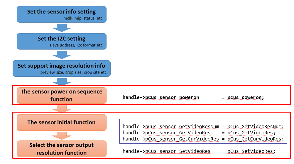
This document introduces the initial process of transplanting the sensor according to the process in the figure above.
4.6. Select the Sensor Driver Resolution
static int pCus_SetVideoRes(ms_cus_sensor *handle, u32 res_idx)
{
    imx415_params *params = (imx415_params *)handle->private_data;
    u32 num_res = handle->video_res_supported.num_res;

    if (res_idx >= num_res) {
        SENSOR_EMSG("[%s] Please check the number of resolutions supported by the sensor!\n", __FUNCTION__);
        return FAIL;
    }

    handle->video_res_supported.ulcur_res = res_idx;

    switch (res_idx) {
        case 0:
            handle->video_res_supported.ulcur_res = 0;
            handle->pCus_sensor_init = pCus_init_8m_20fps_mipi4lane_linear;
            vts_30fps = 2813;
            params->expo.vts = vts_30fps;
            params->expo.fps = 20;
            Preview_line_period = 17778; // 49.86ms/2813 = 17725ns
            handle->data_prec = CUS_DATAPRECISION_10;
            break;
        case 1:
            handle->video_res_supported.ulcur_res = 1;
            handle->pCus_sensor_init = pCus_init_6m_30fps_mipi4lane_linear;
            vts_30fps = 2250;
            params->expo.vts = vts_30fps;
            params->expo.fps = 30;
            Preview_line_period = 14815;
            handle->data_prec = CUS_DATAPRE
        ...
        ...
}
4.7. Control the Sensor implement function flow
{
    handle->pCus_sensor_AEStatusNotify  = pCus_AEStatusNotify;
    handle->pCus_sensor_GetAEUSecs      = pCus_GetAEUSecs;
    handle->pCus_sensor_SetAEUSecs      = pCus_SetAEUSecs;
    handle->pCus_sensor_GetAEGain       = pCus_GetAEGain;
    handle->pCus_sensor_SetAEGain       = pCus_SetAEGain;
}


4.7.1. Notify API for sensor setting action to HW

5. Supplement
5.1. Install the sensor driver parameter
SigmaStar sensor driver provides several installation parameters that can be used when installing the sensor driver. Here are the parameters and instructions as below:
| Parameter | Description |
|---|---|
| chmap | Specify SoC Channel pad for sensor |
| lane_num | Specify Sensor linear mode MIPI lane number |
| hdr_lane_num | Specify Sensor hdr mode MIPI lane number |
| i2c_slave_id | Specify Sensor i2c slave id |
For example:
insmod imx335_MIPI.ko chmap=1 lane_num=4 hdr_lane_num=4 i2c_slave_id=0x20
If the above parameters are not used when installing the sensor driver, the default values in the sensor driver are used.
5.2. Verify and Debug
5.2.1. cat /sys/class/mstar/vif0/vif_ints
At the same time you can open telnet and enter the following cmd to confirm the VIF and ISP status. Usually 30fps means that a frame period is 33.3ms.
/ # cat /sys/class/mstar/vif0/vif_ints
== VIF CH-0 ==
Interval(ns)                  : 33309000
VREF_RISING                   : 6147
VREF_FALLING                  : 6149
LINE_CNT_0                    : 2
LINE_CNT_1                    : 2
5.2.2. cat /sys/class/mstar/vif0/vif_info
Confirm the information of the sensor signal received by VIF device
/ # cat /sys/class/mstar/vif0/vif_info
== VIF CH-0 ==
INTF_MODE = 4
CH_EN: 1
SRC: MIPI0
INPUT_FMT: RGB
PIX_FMT: 12 bits
HDR_EN: 0
 HDR_CH: VC0
CROP_EN: 1
CROP_START_X: 0 - 1919
CROP_START_Y: 0 - 1079
PIXEL_CNT: 1920
LINE_CNT: 1080
5.2.3. cat /sys/class/mstar/isp0/isp_ints
If the transmission speed of one line or pixel per frame is too fast, even if the VIF can receive the image data normally, there is no guarantee that the ISP can process it immediately, it causes isp fifo full.
/ # cat /sys/class/mstar/isp0/isp_ints
frame_count                       : 1089
u32FrameIntervalNanoSec           : 33332 us
ISP_FIFO_FULL                     : 0
INT_PIPE1_FIFO_FULL               : 0
ISP_BUSY                          : 1089, 06.952374
ISP_IDLE                          : 1090, 06.950575
RDMA0_DONE                        : 0
RDMA1_DONE                        : 0
WDMA0_DONE                        : 0
WDMA1_DONE                        : 0
WDMA6_LINE_HIT                    : 0
WDMA6_DONE                        : 0
ISPIF_VSYNC                       : 1089, 06.952046, 0
AE_DONE                           : 1088, 06.950279, 1934
AE_DONE period                    : 31565 use